- 您现在的位置:买卖IC网 > Sheet目录251 > SFCF64GBH2BU4TO-I-NU-517-STD (Swissbit NA Inc)FLASH SLC UDMA/MDMA/PIO 64GB
�� �
�
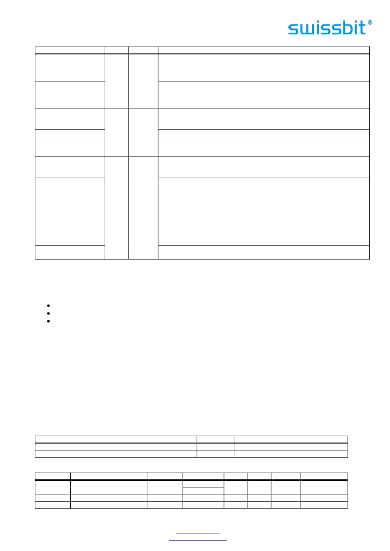
�Signal� Name�
�-DDMARDY�
�(True� IDE� Mode� –� Ultra�
�DMA� Write� Mode)�
�DSTROBE�
�(True� IDE� Mode� –� Ultra�
�DMA� Read� Mode)�
�–� WE�
�(PC� Card� Memory� Mode)�
�–� WE�
�(PC� Card� I/O� Mode)�
�–� WE�
�(True� IDE� Mode)�
�WP�
�(PC� Card� Memory� Mode)�
�Dir.�
�I�
�Pin�
�36�
�Description�
�In� True� IDE� Mode,� when� Ultra� DMA� mode� DMA� Write� is� active,� this� signal� is�
�asserted� by� the� host� to� indicate� that� the� device� is� read� to� receive� Ultra� DMA�
�data-in� bursts.� The� device� may� negate� –� DDMARDY� to� pause� an� Ultra� DMA�
�transfer.�
�In� True� IDE� Mode,� when� Ultra� DMA� mode� DMA� Write� is� active,� this� signal� is� the�
�data� out� strobe� generated� by� the� device.� Both� the� rising� and� falling� edge� of�
�DSTROBE� cause� data� to� be� latched� by� the� host.� The� device� may� stop� generating�
�DSTROBE� edges� to� pause� an� Ultra� DMA� data-out� burst.�
�This� is� a� signal� driven� by� the� host� and� used� for� strobing� memory� write� data� to�
�the� registers� of� the� CompactFlash� TM� Storage� when� the� card� is� configured� in� the�
�memory interface mode. It is also used for writing the configuration registers.�
�In� PC� Card� I/O� Mode,� this� signal� is� used� for� writing� the� configuration� registers.�
�In� True� IDE� Mode,� this� input� signal� is� not� used� and� should� be� connected� to� VCC�
�by� the� host.�
�Memory� Mode� –� The� CompactFlash� TM� Storage� Card� does� not� have� a� write� protect�
�switch.� This� signal� is� held� low� after� the� completion� of� the� reset� initialization�
�sequence.�
�I/O� Operation� –� When� the� CompactFlash� TM� Storage� Card� is� configured� for� I/O�
�Operation� Pin� 24� is� used� for� the� –� I/O� Selected� is� 16� Bit� Port� (-IOIS16)� function.� A�
�Low� signal� indicates� that� a� 16� bit� or� odd� byte� only� operation� can� be� performed�
�–� IOIS16�
�(PC� Card� I/O� Mode)�
�O�
�24�
�at� the� addressed� port.�
�In� PC-Card� mode,� the� IOIS16� signal� does� not� work� correctly.� If� a� host� uses� this�
�signal,� this� may� result� in� 16� bit� accesses� being� changed� to� two� 8� bit� accesses.�
�Depending� on� the� address,� this� may� fail.� A� simple� test� will� show� the� C-400�
�compatibility� to� a� certain� host.� If� the� C-400� cards� can� be� recognized� (Identify�
�Device� and� MBR� data� is� read� out� successfully),� then� this� PC� card� issue� will� likely�
�not� affect� the� operation� in� this� host.� (1)�
�–� IOCS16�
�(True� IDE� Mode)�
�In� True� IDE� Mode� this� output� signal� is� asserted� low� when� this� device� is�
�expecting� a� word� data� transfer� cycle.�
�1)�
�If� you� have� host-card� incompatibilities� please� contact� Swissbit.�
�5.2� Electrical� Specification�
�Table� 12� defines� the� DC� Characteristics� for� the� CompactFlash� TM� Memory� Card.� Unless� otherwise� stated,� conditions�
�are:�
�Vcc� =� 5V� ±� 10%�
�Vcc� =� 3.3V� ±� 5%�
�0� °C� to� +85� °C�
�The� card� interface� is� driven� with� 3.3V.� The� input� pins� are� 5V� tolerant.�
�The� High-Speed� IDE� lines� are� terminated� with� serial� resistors� as� specified� in� the� ATA� specification� to� improve� the�
�signal� quality.�
�Table� 12� shows� that� the� Card� operates� correctly� in� both� the� voltage� ranges� and� that� the� current� requirements� must�
�not� exceed� the� maximum� limit� shown.�
�The� current� is� measured� by� connecting� an� amp� meter� in� series� with� the� Vcc� supply.� The� meter� should� be� set� to� the�
�2A� scale� range,� and� have� a� fast� current� probe� with� an� RC� filter� with� a� time� constant� of� 0.1ms.� Current�
�measurements� are� taken� while� looping� on� a� data� transfer� command� with� a� sector� count� of� 128.� Current�
�consumption� values� for� both� read� and� write� commands� are� not� to� exceed� the� Maximum� Average� RMS� Current�
��Table� 13� shows� the� Input� Leakage� Current,� Table� 14� the� Input� Characteristics,� Table� 15� the� Output� Drive� Type� and�
��Table� 12:� Absolute� Maximum� Conditions�
�Parameter�
�Input� Power�
�Voltage� on� any� pin� except� VCC� with� respect� to� GND�
�Table� 13:� Input� Leakage� current� (1)�
�Symbol�
�VCC�
�V�
�Conditions�
�-0.3V� to� 6.5V�
�-0.5V� to� 6.5V�
�Type�
�IxZ�
�IxU�
�IxD�
�Parameter�
�Input� Leakage� Current�
�(if� not� pulled� up� or� down)�
�Pull� Up� Resistor�
�Pull� Down� Resistor�
�Symbol�
�IL�
�RPU1�
�RPD1�
�Conditions�
�V� IH� =Vcc�
�V� IL� =� GND�
�Vcc� =� 5.0V�
�Vcc� =� 5.0V�
�Min.�
�-10�
�50�
�50�
�Typ.�
�Max.�
�10�
�500�
�500�
�Units�
�μA�
�kOhm�
�kOhm�
�Swissbit� AG�
�Industriestrasse� 4�
�Swissbit� reserves� the� right� to� change� products� or� specifications� without� notice.�
�Revision:� 1.00�
�CH-9552� Bronschhofen�
�Switzerland�
�www.swissbit.com�
�industrial@swissbit.com�
�C-440_data_sheet_CF-HxBU_Rev100.doc�
�Page� 16� of� 102�
�发布紧急采购,3分钟左右您将得到回复。
相关PDF资料
SFN08B4702CBQLF7
RES ARRAY 47K OHM 7 RES 8-DFN
SFP1050-12BG
FRONT END AC/DC 1050W 12V
SFP450-12BG
PWR SUP 450W 12V 36.6A W/STANDBY
SFSD1024N1BN1TO-I-DF-151-STD
FLASH MICRO SD CARD IND S-200 1G
SFSD2048L1BN2TO-I-DF-151-STD
FLASH SECURE DGTL CARD SD 2G
SFSD4096L1BN2TO-I-Q2-141-STD
FLASH SECURE DGTL CARD SDHC 4G
SFSD8192N1BW1MT-E-QG-111-STD
FLASH MICRO SD 8GB EXT TEMP
SFUI4096J1BP2TO-I-DT-211-STD
FLASH DRIVE USB MODULE U-110 4G
相关代理商/技术参数
SFCF64GBH2BU4TO-I-NU-527-STD
制造商:SWISSBIT 功能描述:CFC C-440 DENSITY INDUSTRIAL - Trays 制造商:SWISSBIT NA INC 功能描述:FLASH CARD 64GB IND C-440 制造商:Swissbit 功能描述:Memory Cards 64GB IND COMPACT FLASH SLC NAND C440
SFCF8192H1BO2TO-C-Q1-523-SMA
制造商:SWISSBIT NA INC 功能描述:FLASH
SFCF8192H1BO2TO-C-Q1-533-ZP1
制造商:SWISSBIT NA INC 功能描述:FLASH
SFCF8192H1BO2TO-C-Q1-543-SMA
制造商:SWISSBIT NA INC 功能描述:FLASH
SFCF8192H1BO2TOIQ1523SMA
制造商:Swissbit 功能描述:Flash Card 8G-Byte 3.3V/5V CompactFlash 50-Pin
SFCF8192H1BO2TO-I-Q1-523-SMA
功能描述:FLASH SLC UDMA/MDMA/PIO 8G RoHS:是 类别:存储卡,模块 >> 存储器,PC 卡 系列:C-320 标准包装:30 系列:- 存储容量:8GB 存储器类型:存储卡 - Extreme III SD?
SFCF8192H1BO2TO-I-Q1-533-ZP1
制造商:SWISSBIT NA INC 功能描述:FLASH
SFCF8192H1BO2TO-I-Q1-543-SMA
制造商:SWISSBIT NA INC 功能描述:FLASH